Aquarium Plumbing Basics
When you set out to plumb an aquarium set-up with a sump, the more planning / thought you put into the original set-up, the better it will be in the long run. This is not a very hard thing to do at all, if you focus on the basics and understand them. I tend to think of it in flowing different steps: A) Planning of your flow rates, B) planning the material types and sizes, and C) installation / set-up of the plumbing system. All of what you are about to read below is based on my experiences with various data from some North American manufactures of plumbing products (IPEX, Canplas, and Boshart) which is also detailed in the American Society for Testing and Materials (ASTM) standards.
I will explain what I mean by each step then I will show you examples from one of my reef tanks
Note: you have to keep in mind, there may be variation in the plumbing products available to you based on the national building codes of the country that you live in along with local regulations, says Jet Plumbers Arvada Drain Cleaning Services. The below applies to almost all of Canada and the United States. The products available to you may vary.
A) Planning Flow Rates
With every system, you need to know how much flow you will need. Typically this is calculated in gallons per hour (GPH). For example, most people feel a flow through their sumps of 10 times the display tank volume is suitable. If you have a 120 gallon display tank, then that would mean you will need 1200 gph of flow. But that is only a general guideline. Your exact flow rate could be higher or lower depending on the equipment in the sump or what you are planning to use the sump for. Once you have determined the flow rate you will need, you will need to apply this target flow rate differently to both your drain line and your return line. The 10X flow rate is typically a good base to start working from and can apply to almost all typical salt water setups. Some people prefer high flow through their sumps. Fresh water setups typically use a little lower flow rates, around 4 to 6 times the display tank volume is more common.
Drain lines are the lines bring water down from the display tank into the sump. There are many different approaches to achieving this, but mainly fall into one of two categories: Siphon based systems, or a Gravity system (which involves drilling a hole in your tank). With either set-up, one of the bigger factors to consider is the flow rates under extremely little to no pressure. Both types of drains are very similar in GPH (no real significant differences) and these types of drains are discussed in my example here the end of the article. Whatever choice you make, you have to make sure the drain line can also handle the flow you want to put through the sump.
Return lines are the pressurized lines that run from the return pump back into the display tank. There are three factors that are very important to consider here: flow rates, pressure, and the types and numbers of fittings used.
B) Planning Material Types and Sizes
With all aquarium setups (both salt water and fresh water), you have to make sure the pipe and fittings you use to plumb your system are both meant for potable water (can safely handle drinking water) and is resistant to corrosion and scaling. You can ensure those requirements are met by using one of the below material types
ABS (Acrylonitrile Butadiene Styrene). Typically only used for drainage in homes as it cannot withstand much pressure or heat. This is typically black in color. ABS is the cheapest pipe and fittings that can be used. It is only suitable for drain lines and should not be used for pressurized applications.
PVC (Polyvinyl Chloride). Most commonly used as it can handle a range of pressure and some heat. It can be used in residential and commercial drinking water supply (cold water supply only). It usually is the most economical choice for almost all aquarium setups as well as being the most commonly used for pressurized and drain lines.You can get it in both in flexible and rigid pipe (flexible PVC has lower pressure ratings). This is typically white in color.
CPVC (Chlorinated Polyvinyl Chloride). Most commonly used in commercial and/or industrial applications. Can handle both hot and cold drinking water supply. This is typically a shade of grey in color. Although this can be used in an aquarium set-up, it is one of the more expensive options.
PEX (Cross-Linked Polyethylene). Slowly becoming the most used product in the construction of new homes for both the hot and cold drinking water supplies. Is made both in flexible and rigid pipe while maintaining the same pressure rating. PEX is typically a white, almost transparent color. Although this can be used for both pressurized and drain lines, it also is a very expensive option as you need special tools when connecting PEX fittings.
PVC and CPVC are also available in different grades / thicknesses to allow for higher pressure and higher heat limits on both the pipe and fittings. This is done through using the Schedule System. The wall thickness of the pipe and fittings is designated with a “schedule” number. The range from sch (schedule) 40 all the way up to sch 160. Typically you will find sch 40 (regular) and schedule 80 (extra heavy) available in most hardware stores. Schedule 120 and 160 is not commonly used or available in retail stores.
For PVC pipe and fittings, The general rule of thumb is that any pressurized application that would require your set-up to have below 2 inch pipe can / should be completed in schedule 40. Anything higher (ie.. 2 and 2 ½ inch applications) would require schedule 80. That may vary based on exact conditions. You would not have to worry about up-grading to sch 80 pipe unless your system would require around 5,500 gph of flow (or higher flow) through a single plumbing line.
For ease of identification, most manufactures make regular PVC (sch 40) white in color while they make sch 80 in grey. Not all manufactures will do this. It’s always best to read the markings and labeling on the fittings or pipe just to make sure.
The below charts summarized flow rates by: no pressure, average pressure applications, and the maximum pressure that the pipe and fittings can handle in standard PVC (standard = sch 40). Once I start to talk about an example of plumbing a sump, I will be referring back to these charts
(GPH = Gallons Per Hour )

And just to clear up some of the terminology used, ID = Inside Diameter while OD = Outside Diameter.
Loss of flow
Once thing to keep in mind, when planning your plumbing set-up the pump should be the last thing you choose. The reason for this is that you need to know how much loss of flow you will have from your plumbing design. Each time you add a 90 degree elbow, or a swing check valve, you will lose some flow because of these additions to your plumbing line. The below list are more of a rule of thumb with calculating flow loss of your pressurized return line only. They may not be 100% accurate, as many other factors can effect these calculations. They will be close enough for you to get an accurate estimate of the flow reduction. The below factors will become very important when planning your set-up.
• A loss of 75 to 125 GPH for each foot of height (from the pump to the display tank return)
• A loss of 50 to 75 GPH for each 90 degree elbow
• A loss of 30 to 50 GPH for each 45 degree elbow
• A loss of 50 to 75 GPH for each swing check valve
• A loss of 20 to 40 GPH for each ball valve
• A loss of ~ 3 to 5 GPH for each union
I will also be referring back to this information latter when I show how I planned the plumbing layout of my sump.
C) Planning the set-up/Installation.
We have already discussed the typical sizes and material available for your pipe, now it might be best to talk about fittings, other than the more common fittings pictured below. This will help you when it comes time to plan each line in your plumbing.
Below are some of the other fittings that typically use and most likely can be used in your set-up.
PVC Unions

These are very useful fittings to have in your set-up. It can allow you to quickly disconnect a part of the system and then reconnect again without have to worry about gluing or resealing anything. A perfect example of this would be using a union to connect your return pump to the system. This way, you could quickly remove the pump from the plumbing, clean it, then reconnect the pump with a minimal amount of down-time. On more complicated set-ups, it allows for building the plumbing system in different sections before quickly connecting it together. Using unions is also a good idea when working in tight / small paces as you can assemble the lines elsewhere before connecting the system together. They come in standard and sch 80 PVC for both socket weld and screwed / threaded connections
Bulk-head flanges

On a set-up that uses a tank with drilled holes in the glass, the bulk head flange attaches to this hole allowing us to attach plumbing lines to each side of the hole while giving us a water tight seal to the glass that will withstand pressure. They can also come in regular and sch 80 PVC for both socket weld and screwed / threaded connections. The most common bulk head flanges are threaded.
Valves
There are three main types of valves that are the most common in aquarium set-ups, swing check valves, ball check valves, and ball valves. Each has a different use in a plumbing setup.
Swing check valves allow for water movement in only one direction. It has a plate / door inside the valve which will swing open when pressure is apply to only one side of it. It will swing shut when pressure is applied to the other side. Many people install check valves on the return line to their main tank to help prevent water draining back into the sump should the return pump stop working (ie.. if the power goes off). There are a few different types of check valve out there, but the swing check valve is among the most common one used. The better quality swing check valves are design to work without a spring assembly but they will restrict the flow a little. They are available in regular and sch 80 PVC for both socket weld and screwed / threaded connections. The diagram below will show you how the inside of a swing check valve works. Exact designs vary among different manufactures

Ball check valves have the same purpose as compared to a swing check valve. Ball check valve are another type of very simple check valve to only allow water to flow in one direction through the valve. The valve uses a PVC ball and the force of the water to work. When water is flowing through the valve in the intended direction of flow, the water will hold the ball up against 4 PVC rails inside the body of the valve. These rails allow enough spacing around the ball for water to freely move around it. Only one of the internal rails is shown in the below diagram.

When the direct of the flow changes to the opposite of the intended direction of flow, the ball will be pushed back to rest on a rubber gasket and prevent any flow from getting past it.

The below is a picture of a ball check valve that I used on a larger reef tank. The picture was taken early on when plumbing it all together.

Please note, a ball check valve works best when installed on a vertical line, not a horizontal line like pictured above.
Ball valves are used to control flow and/or to shut off flow. It is basically a ball with a hole drilled completely through it that is also has the same inside diameter as the pipe it is connected to. When the handle is turned in the same direction of the pipe, the hole lines up with the pipe and the valve is fully open. When the handle is turned in the opposite direction of the pipe, the hole turned the other way and the valve is completely closed. These are also available in regular and sch 80 PVC for both socket weld and screwed connections.

I would refer you to the below article with some more detialed information about valves commonly used on sumped aqauriums
https://www.reefaquarium.com/2013/aquarium-plumbing-valves/
Miscellaneous adapter / fittings
There are a ton of different fittings designed to be used in certain situations that you may come across like: reducing sizes (glued or threaded or both), increasing sizes (glued or threaded or both), going from threaded to glued fittings, or going from glued to threaded fittings. I’ve only mentioned and provided pictures of a few of those types of fittings here to give you an idea of what is available out there.

Drilled or not drilled
One of the last things you will need to decide is if your display tank will be drilled or not. If the tank will be drilled, it would also be recommended that you have a internal or external overflow for the drain line. I always recommend a drilled tank.
Putting it all together
As previously mentioned, there are two traditional ways of connecting your plumbing system together when using PVC and/or ABS materials. One method involves using a combination of threaded fittings and solvent weld (AKA gluing), and a second of using only solvent welded (glued) fittings.
Using Threaded Fittings
This is a fairly easy method to use. There are three things you have to keep in mind:
1) You will need to use thread tape. In pressurized lines, this will fill in the small gaps between the threads and prevent any leaks. It will also help to keep the two fitting tight together. Just make sure you wrap the tape around the threads very tightly and in the opposite direction of the threads so it will not become “un-wound” or bunch up in one spot when you screw the fittings together (see below pic).
2) Do not use / connect threaded fittings made from different materials together. The reason being is that different materials will have different expansion rates when/if they are heated up or get very cold. This will likely cause leaks even when thread tape is applied.
3) Unless you are a skilled pipe fitter by trade, you will need to use adapters to transition from threaded fittings to solvent weld fittings. The reason being is that at some point you are going to need to have a piece of pipe cut to fit a portion of one of your lines. Unless you can have the ends thread to the exact length and depth of the fittings, you going to have to use solvents and adapter to transition between the two connection methods.

Solvent Welding
This is my preferred method. When it is done correctly the bond between the fittings will outlast the pipe and fittings themselves. Solvent Weld is commonly referred to as gluing even though it is not a gluing process at all. The solvent cement actually starts to melt or soften the outer layers of the PVC or ABS when it is applied to the pipe and fitting. When the fitting and pipe are then placed together, the soften materials will now become fused together. It will start to harden in sections, become dry to the touch in about 10 minutes, and will be fully cured and safe to use in 24 hours.
There is a specific type of solvent for each type (and sch) of plastic pipe. It is extremely important to use the correct solvent as it contains an element of the material dissolved in chemical called tetrahydrofuran which allows for the material of both peaces to become fused together. If you use the incorrect solvent, the bond between the two fittings will fail over time assuming one forms at all. When correctly used, the bond between the two fittings will be unbreakable.
With certain types of plastic pipe and fittings, a primer is also suggested for use. This mostly applies to the thicker plastics (like sch 120 or 160), or fittings with finishes that looks like they are highly polished with a mirror-like finish. For PVC and ABS applications, primers would not be required. Additionally, when joining different types of materials (like Regular PVC and sch 80 PVC) you will need both a primer and a solvent meant for using both types of materials or you will not get a bond that will last over time. These are commonly referred to as transition cements / glues.
I would also recommend using a solvent that has low VOC and (in Canada and the USA) meets on of the following ASTM standards: ASTM D2564 ASTM F656, ASTM D2235, ASTM F493, ASTM D3138, and ASTM 2235. Those two statements (Low VOC and one of the previously listed ASTM standards) should appear in the bottle.


Below is how I put together the plumbing set-up for my 120 gallon tank using a 55 gallon tank as the sump. I tried to lay it out in little more detailed steps that I took going from planning the set-up right to installing the plumbing. Please keep in mind, this is just one way to set-up and install plumbing in a sump setup. There are many other way to approach this. I am only speaking to the way that I have done this to hopefully give you ideas on how to approach your set-up.
Now for the first stage – A) Planning the flow rates
Step 1 : How much flow through the display tank
I had decided that I would use the traditional rule of thumb. I set my goal to have 10 times the display tank volume flowing through the sump. That flow rate is very close to the maximum recommended flow for my skimmer and I can add a powerhead to the live rock compartment as that would be the only compartment which requires a higher flow rate. As I have a 120 gallon display tank, that would mean I need 1,200 GPH of flow. But I am willing to settle for anything between 1,000 and 1,400 gph
Step 2: Drilled tank or not (gravity feed or Siphon based drain line) ?
When it comes to gravity based drains, there are two common approaches to control the air/water mixture in order to get a silent drain. One approach involves using two drain lines , one line containing a valve to restrict the water flow to match the air flow (resulting in a silent drain), and the second is used as a backup drain should the first main drain line become clogged. This type of approach as a few different common names, like: herbie overflow, bean animal, ocean to ocean
The second approach involves using a single drain line and controlling / restricting the airflow to create a silent drain. This is commonly referred to as a Duriso Standpipe. This is my preferred approach as the plumbing is easier to setup and, in my own opinion, less likely to become clogged as you are not restricting the flow of water inside the drain.
As I purchased a new tank, I got one that was already drilled for a return line and a drain line with an internal overflow, I set up a duriso standpipe. Gravity based drains are my preferred method to set up a tank as you can calculate the amount of water that can drain back into the sump should your return pump stop working preventing any water on the floor. Both of my reef tanks have been set-up that way as we get frequent power failures were we live. I chose gravity feed system over a siphon based system for a few different reasons. The least of which is that I feel I can trust gravity feed system not to fail and a gravity based system makes the least amount of noise when assembled correctly.
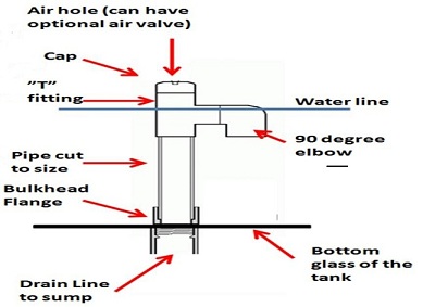
The pic below shows a Durso stand pipe along with one that I used on my 90 gallon reef tank

Water flows in through the 90 degree elbow at the top and down the pipe through the bulkhead flange and into the plumbing line to the sump. At the very top is a air hole which allows a steady, even flow of water. This will give you a extremely quiet drain line. There is no real set size for the air hole. It can be trial and error. I had made a adjustable air hole by drilling a 5/8 inch hole through the side of the cap and the side of the standpipe. You adjust it by slighting turning the cap to make the hole smaller or bigger which controls the flow of air. Through using an adjustable air hole, you can get the maximum flow and keep the drain extremely quiet (pic below). You can also use a oversized hole (such as ¾ inch) and an air valve as well.
The one disadvantage of a Durso standpipe with a internal overflow is that uneaten food, sludge, etc, can accumulate in the bottom and sides of the overflow over time. This is a minor problem, and really not a big deal. But for this reason I recommend using all slip fittings in the construction of the standpipe, and not gluing the standpipe to the bulkhead. If left unglued, when the interior of the overflow accumulates too much sludge, you can simply scrub around inside the box to loosen things up and pull the standpipe out of the bulkhead. If you choose to drill your own tank, the below link explains the steps of that process.
http://www.aquaticcommunity.com/aquariumforum/showthread.php?t=76407
Just remember you must make the hole ½ to ¾ inches larger than the pipe and fitting size the bulk head flange is rated for. For example, if you want a 1” bulk head flange you will need a 1 ¾ inch hole in your tank.
The Siphon set up is a little more involved. Below is the most common design used.

It is designed to be a non-break siphon. If the power goes out, the tank will only drain down to the point of the intake being out of the water and it is said to start draining again once the return pump comes back on the water line is above the intake. I have never tried one so I do not know how well they actually work. I only wanted to mention them here as an alternative to a stand pipe with a drilled tank. The below link can help you build your own siphon based drain system should you chose that type of drain.
http://www.evillabs.net/wiki/index.php/Super_Sucking_Siphon
There are so alternate products available for a siphon based system using pre-assembled overflow boxes like the one in the below link. These products are typically available in stores that carry products for salt water aquariums. One example is in the link below. Once again, I have never used one of these but it is a possible option to look into should you have a tank that cannot be drilled.
http://www.jlaquatics.com/product/of-cs100/CPR+C-Siphon+Aquarium+Overflow+-+CS100+Deluxe+%28800GPH%29.html
B) Material Types and Sizes
Step 3: Choose the pipe and fittings sizes and material types.
First I determine the size of pipe that I will need for my return line. You can always cheat at this step and just go with the same size of pipe and fittings as the outtake on your return pump. But if I did not know that, I would base my decision on a flow rate of 1200 GPH and the fact that I want to use flexible PVC. This leads me to choose a one-inch line. As flexible PVC has a working pressure of 100 psi and at that pressure a 1 inch line will give me ~2220 gph which is more than enough. For a drain line (including the durso stand pipe) I chose 1 ½ inch line as the will give me about 1400 gph of flow which is a little more than I need just to be safe. Either PVC or ABS will be good for this application. I used PVC as I had some left over from another sump I had set-up.
C) Planning the set-up/Installation.
Step 4: plan the layout.
I drew a simple diagram of how I wanted to put the plumbing together. I kept in mind how much room I had in the stand, the size of the sump, and where I wanted to put all of the equipment in the sump so there would be no plumbing lines in the way. I also did not require a swing check valve on either the return line or drain lines as I made sure the sump has room for all the drain-back into the sump from the main tank should the return pump stop working.

Step 5: Calculate the flow loss on the return line.
Based on: 4 feet of height, three 90 degree elbows, two unions, and one ball valve, there would be a estimated loss of 650 gph. This would mean that I would need a return pump with a flow of 1650 to 2100 gph. As the drain line does not have any significant pressure in it, any flow loss due to only two elbows and a union would not be significant.
Step 6: Chose a return pump
I ended up getting a pump with a 1800 gph flow rate which results in a over flow through the sump of 1,150 gph. This also means I do not have to up-grade the size of my pipe and fittings, or increase the size of the. All of the other factors that go into selecting a return pump is a topic best left for another article.
Step 7: Assemble
After getting everything I needed, along with the proper cements, I got started. I first measured and cut the first few pieces of pipe and put together the plumbing lines as I went. I did not use any glues at this point. Once I had everything built and place just the way I wanted it, I marked each joint with a black marker. That way when I took it apart to apply the cement, I just had to line up the two marks on each connection to make sure it was put it back together just as I had dry fitted it together. This gives me the options to adjust things before gluing as well as gluing some of the plumbing system outside where I don’t have to worry as much about making a big mess
While setting the fittings together I had realized I forgot to add a line to run a media reactor. I added that line to the return line using a “t” fitting. This will not have a significant effect on the overall flow
Step 8: Test.
After letting the newly bonded fittings cure for 24 hours, I filled it up with freshwater and fired up the return pump. I found one small leak which was quickly fixed by tightening the bulk head flange. I let it run for a few days until I had the air intake adjusted so the drain line had the least noise.
And just a few pics of the actual set-up


Please feel free to start a thread in the forum to ask any questions you may have. If you are not already a member, you will need to sign-up first.
http://www.aquaticcommunity.com/aquariumforum/forumdisplay.php?f=62
For more detialed information about the different choices that you have for plumbing materials, I would refer you to the below article here
https://www.reefaquarium.com/2013/plumbing-pipe-ans-fittings/
You truly are the man Cliff – very comprehensive but still concise. Thanks for passing on your knowledge, its going to help me a lot.
Great article! I’m using the siphon method for my 125 gal freshwater tank. Saltwater is something I’ll tackle down the road. Thank you for taking the time to pass along this information.
good article it really helped me understand what I had been searching for, Thank you
Excellent article, it answered every question I had! Huge thanks are in order for the time that you’ve put into this.
Great article. I found this while googling around ball check valves for aquaria.
Question for you, Cliff, do you think a check valve would be necessary in a non-sump, in-line filtration system? Specifically, I am running a series of Lifegard tubes. The plumbing is basically a simple over-the-lip siphon and a return pipe out of PVC.
The only info I can find recommends check valves back into the sump. Should my pump fail, I don’t know if I would need one for this system. The return is submerged a bit, so it may provide a counterbalance for the closed loop.
If you are using a canister filter, you do not need any type of check valve, provided you have the intake and return lines both in the tank. When both lins are in the tank nothing will happen when/if you unplug the filter
Finding this post solves a porlbem for me. Thanks!
Actually I like to seeing some aquariums because beautiful fish’s in available this, but these types of plumbing systems are using in aquarium it thing is completely new for me. Yes after reading this blog I am understand that why plumbing system is important on aquarium with fish.
You’ve got to be kidding me-it’s so transpaernlty clear now!
Hello I have a 450 litre tank with a 32mm pipe for the outlet of the tank on the back of the tank with just the pipe going in to tank any help to make it flow out better many thanks I can email pics to u cheers dan
Daniel, It might be best if you were to go to our forum and post some pics and your questions there. It would be a whole lot easier for me to be able to help you with your set-up that way
http://www.aquaticcommunity.com/aquariumforum/index.php
Thank you so much for this post.
I’m setting up a 55 corner reef tank and have only had nano cubes in the past. My tank is older with all non-tempered glass (I hope) and understanding the many different options for plumbing and usage of a sump has had me overwhelmed.
I appreciate this information.
Debbie
I found your information very very helpful. Thank you so much. I do have a few questions though… I am putting a sump in my basement. This is my first time ever doing plumbing. It would be 10 feet from the tank to the sump. The loss of GPH would be around 1455. You said using a 1″ flexable PVC line for the return would give you 2220 GPH. Which would make my GPH around 765 correct? What would be the best way to increase this? I wanted to get around 1000 at the very least. Would increasing the pipe size for the return line help. maybe to 1 1/2 in? Any suggestions would be great. The tank size is 180 gallon and the overflow is 1200 GPH.
Julie: I’m afraid increasing the size of the return line will not provide you with the results you are looking for. I would suggest looking into a larger return pump. You also have to keep in mind that after the first few months of use, a return pump’s GPH will usually drop after the pump break-in period is over. I would suggest a pump in the 2000 (or more) GPH range. You can always plumb in a by-pass to reduce the flow a little if it works out to be a little more flow than what your drain line can handle. It certainly would be a good idea to maximize the flow your drain line can handle, plus have a little extra should you ever want to add anything, such as a media reactor or a UV.
Wow, awesome blog layout! Thanks For Your article about Aquarium Plumbing Basics | Saltwater Aquarium .
Great article and I have a quick question on the loss GPH. You have listed:
• A loss of 75 to 125 GPH for each foot of height (from the pump to the display tank return)
• A loss of 50 to 75 GPH for each 90 degree elbow
• A loss of 30 to 50 GPH for each 45 degree elbow
• A loss of 50 to 75 GPH for each swing check valve
• A loss of 20 to 40 GPH for each ball valve
• A loss of ~ 3 to 5 GPH for each union
Do you have any idea how much a full loop would lose per gallon? I have off of the sump in line under the tank a loop prior to entering the sump. I have a feeling this is causing sigificant slow down. The people that installed my tank did it to lessen the drain noise and bubbling in the sump. I have the same 120 you do with a Mag 12 can it feel like it’s slow flo.
Matt: I would guess one complete loop would be close to the same effect (or a little more) as a 90 degree elbow and there is a more gentle re-direction of the flow. That would also depend on the length of the hose as well. I have never found a very credible reference for how to calculate that, nor have I actual calculated it myself. Just a educated guess on my part.
What I would suggest is signing up on our forum and starting a thread to ask this same question. If you post some pics of your set-up I’m sure we all can figure out how to increase the flow to the tank.
http://www.aquaticcommunity.com/aquariumforum/index.php
Good stuff, thank you for this. As a contractor this really helps keep me fresh…. Thanks Again…
does any one have a design for an automatic water changing system
Cliff….Help.
Ok, here’s what I have cookin’
55 gal tank “freshwater” for Discus display.
I want to put the sump refugium in the basement directly under the aquarium above.
11’-0” from return pump to tank. My configuration will not support one any closer as my aquarium is place in the wall with a bar on one side and a pantry on the back side. Strange I know…but I placed it in the wall and currently use a small fluval 330..not good.
I am constantly doing water changes and dealing with algae build up.
Calculations: (did this a couple different ways but will post most recent)
Return pump: 1” pvc 2200 GPH
Drain Line: 1 ½” 1400 GPH (using glass holes direct drain line)
55 gal tank @ 10x = 550 GPH
Loss of flow:
@ Return line
(2) 90 degree unions at aquarium @ 75 GPH= 150 GPH
(1) T – Union – overflow back to sump @ 5 GPH= 5 GPH
(2) Unions @ pump and Aquarium @ 5 GPH= 5 GPH
(1) Ball Valve @ 40 GPH= 40 GPH
(1) Swing Check @ aquarium @ 75 GPH= 75 GPH
11’ return “Average”@ 100 GPH= 1,100 GPH
Total 1,650 GPH LOSS..Help!
Obviously, my Height is the major contributing factor.. the unions, ball valve etc. are major factors.
My Return Pump Options: (Would like to have a ton more as my drain line is 1000+)
Mag Drive 1800 1800-1650 = 150 GPH…no good.
Are my calculations correct? Any suggestions? Pulling my hair out…
David, you are not too far off on your calculations as compared to what I got. You are going to need a serious return pump for that type of head loss. I would suggest looking into a external pump for that type of flow. I would suggest a pump like the ReeFlo Dart/Snapper. Then size your plumbing lines accordingly. You should need a 1.5 inch return line for a pump that will handle more flow even tho the head height will reduce it. Based on the actual flow that will get into the tank, a 1.5 inch gravity feed drain line will be OK
http://www.reeflopumps.com/lowspeedhighflow.html
I would also suggest using a PVC ball check valve and not a swing check valve. Ball check valve are less likely to fail when you need them the most. Just make sure you install it as close to your pump as possible. You will loose about the same in GPH flow as compared to most swing check valves.
Once you have everything set-up, make sure you complete a few power fail tests to make sure the sump can handle the drain back from the tank that you will get. You can adjust the sump compartment sizes base on those results if required.
Hello: David. I currently have 60 gal reef set up. I see you spoke about sump refugium below tank basement. I am looking from basement to top of tank approx 5feet. What was outcome success or not a good idea. My stand is too narrow to place a sump / refugium. Thank you advise/opinion.
This can be done. I have seen a few set-ups like that in person. You have to be very careful to make sure your return pump is strong enough to handle the extra pressure required to maintain the GPH flow when you are dealing with the extra hight of you sump being location in the basement and your tank on the main floor. Carefully calculate the loss from the hight when picking out your return pump
Also using Trigger sump 36 inch capacity of total water volume 34.5 and operating capacity of 23.4…What size return pump is my main question…assuming I have all other factors covered.
Such a great and informative post. Thanks for sharing and keep posting.
Thanks Cliff!
Really appreciate your quick response and suggestions.
I’ll do another run thru on my calcs based on this info.
I have been researching info for my setup for some time now and I stumbled into your presentation.. Such valuable information! I would’ve been very disappointed at my first approach.
My kids will be excited when I get this up and running!
Thank you, Thank you.
Water boy,
David
I see you have some excellent information and charts for flow rates. I would like to suggest the use of sweep 90’s and 45’s wherever possible in lieu of the tight 90’s used by most people. The flow rate restrictions of tight 90’s can add up very quickly in a gravity system but this is also true with pumps. These restrictions can actually be measured with an amp meter but your pump will run quieter and cooler with fewer restrictions. You will be pleasantly rewarded for your efforts.
I currently have a 90gal mixed reef saltwater aquarium with a 29gal sump. I would like to upgrade to a larger sump and make it into a refugium setup; when I do this I would like to also upgrade some of my plumbing, like adding a ball check valve before my pump, some pvc unions, and ball valves just to make things neater etc. I was also considering going to an external pump as to eliminate some heat from my system. I am familiar with glueing pvc plumping and that within a few minutes it is safe to run water through but how concerned should i be with my tank inhabitants?? The last thing I want to worry about is having some of the pvc glue/cleaner running through my system and wiping out my tank!!
Also I notice on larger aquariums most are not using power heads/ fans in their tank; is this because they are running much more gph flow than is necessary to get proper flow through their return lines that they do not need to incorporate power heads/ fans? I find it to be a much cleaner more desirable look not having several power heads/fans cluttering the inside of the tank. I also only have 1- 3/4″ return line that ends in a Y with 2- 3″ flare loc-line nozzles; so I probably wouldn’t be able to get a tremendous amount of flow upgrading my return pump since I only have 1- 3/4″ return line.. I would probably need at least 1 more return line into my tank and they would probably both need to be at least 1″… just assuming here. If that were true that would of course be impractical since I would need to tear my system apart to make changes like that :/
Thanks for your help!
With some of the new low VOC glues on the market today, you should have less of a concern. Most of them typically need around 8 to 24 hours to fully cure and be perfectly safe for your set-up. Follow the curing instructions listed on the bottle of glue and you should be fine.
The powerheads you see in other’s aquariums do serve a pretty vital purpose in a aquarium with live rock. The below link explains that in more detail.
https://www.reefaquarium.com/2012/the-importance-of-water-flow-and-movement-2/
A 1.5 inch return line, even with the Y fitting ending in two line-lock should be able to handle around 2,500 gph of flow with no problems assuming you are talk about sch 40 PVC. That would be more flow than you would ever want in a 90 gallon display tank so there would be no need to change your return line. I would be more concerned about having a drain line (or lines) to handle your planned increase in flow.
I would suggest around 1300 to 1400 gph of flow in your main tank would be a good goal to aim for. Start by planning you sump (what you want in it, the size of the compartments….. and so on). Next plan your drain lines and return lines. You two main goals here would be to make sure your drain line will handle more than your planned flow, as well as identifying all the elements of your return line that will restrict your flow so you can choose the correctly sized return pump for your set up. You would likely want at least one 1.5 inch gravity based drain line (minimum)
I really do like external return pumps, but they can take up a lot of space if your sump is going under your display tank in your stand. Let me know if this answeres your questions
Thanks for the quick reply!
I understand it takes several hours for the pvc glue to cure. The plan I had in mind is to have everything back together and running within a couple hours; and just leave my power heads running in the display tank while I’m making my changes etc..
I understand that the power heads serve their purpose in a living reef aquarium, but I’ve seen much larger setup’s than mine without a single power head; I assume they have multiple drains and returns to get the flow & water movement in the display tank without the need of power heads. I only have 1 (1-1/4″ OD gravity drain) and 1 (1″ OD return line) all the drain plumbing is sch 40 pvc, the return inside the tank is the same except the loc-line; the return under the display tank from the bulkhead to the pump is made of a clear flexible hose.
Thanks for your help!
Is that sch 40 and tiger flex hose that you used in 7? I love it btw, this is exactly what I am looking to do. I am happy someone actually posted an exact diagram on how to do this. I had a great idea on how to accomplish this, but now I have a guide ha.
Thanks for the hard work posting this all up.
Have a good one.
Matt, the flexible tubing used in this article is a form of white PolyVinylChloride (PVC). You will commonly find it on applications like jetted hot tubs that need a flexible PVC tube that will work with regular sch 40 PVC fittings.
I Gone through your Website its really amazing.
very good information on product i got know useful information thanks for this.
Wow, this has to be one of the best written pieces I have read on this topic. Spot on, it was exactly what I was looking for to help me size my return pump.
Thanks!
Thanks Frank, I’m glad you found it helpful
Hi Cliff, i have recently setup a Marine tank with Sump and Durso drain pipe in Weir. I am experiencing some major issues and cannot find a solution. You seem to be the man with the answers so thought I should run it past you.
I have a 32mm drain going down into my sump (hole on top), the return is a 25mm pipe with a D&D H2Ocean Aquarium Pond Flow Pump FL 3000.
The issue i am having is that the drain is struggling hugely and it makes a huge amount of noise. The weir water level drops and rises every 10-15 seconds and makes a loud draining / sucking noise when that happens. How do I stop this and allow the water to flow smoothly? At the bottom of the drain under the tank I have 2 90 degree elbow joints before the pipe enters the water in the sump. The pipe is about 1-2 inches under the water level.
When i reduce the return pump flow to an absolute minimum it calms down and is fine but i feel that level of water flow is not enough.
Anything you can recommend?
It sounds like you do not have have the correct amount of air flow getting into the standpipe, assuming the drain (the way it currently is) is handling the flow of the return pump.
I would suggest getting a new cap for it and drilling just on very very small air hole using the smallest drill bit you can use. Try it for a few minutes and observe. If the duriso is not draining correctly, drill a second hole with the same drill bit and observe for a few minutes. Repeat until it is working the
way you want it. This approach has always worked for me.
Let me know how that works for you, and please keep me posted on your progress
I suffered your web site its very superb.
very good data on product i got apprehend helpful data thanks for this.
PVC Ball Valves Manufacturer
Exellent article this has pointed me in the right direction to design my system
Thanks Oliver, I am very glad to read that you found this helpful
I have an aquarium like this with, this hole on the bottom that I would like to plug and just go with regular outside top Filters. Is there something that u recommend using or where can I find such plug or what to do?
In the past, I have covered drilled holes in aquariums by getting a small peace of glass cut that is about 1 inch wider than the hole and using that almost as a patch. You can secure it over top of the hole using aquarium safe silicone. Just make sure you attach the pc of glass to the inside of the aquarium and the pc of glass you use is as thick as the glass used to build the aquarium.
cliff on a 55 gallon reef aquarium you are saying to use a 1inch drain correct seeing u want a 10x flow rate
cliff i would want to use a 1inch drain on a 55 gallon reef setup using a 20 gallon sump correct seein u want a 10x flow rate in a reef right or wrong
Using that 10X rule of thumb is just really a starting guideline. You will most likely be fine, but here are a few other things to consider before assuming that
You may need to make adjustments deepening on what/how you are using your sump. If it is just for your equipment and skimmer, and the GPH of your skimmer is around 550 GPH, then it will work out fine for you. If not, try to match the flow through the sump with the GHP of your skimmer as best as you can. That will help you get the most out of your skimmer. If you are using your sump for a refugium, then you would want to match the flow going through the sump to better match the requirements of the algae you are growing in there. If you are setting up a algae scrubber on your return line, then you may want to consider even more flow.
As for the pipe size, 1.25 or 1.5 inch drain line would be a little better. 1 inch would work, but I always like having a little extra to work with, in case I want more flow later on.
I plan on coming in threw a sock filter putting a protein skimmer in the front of the sump then flowing into refugium threw a bubble trap then out kinda new to all this an just want to do it right thats why I am asking so you would suggest 1.5 drain it wont be to much thanks for the advice
What is the flow rate of your skimmer ?
Going to use Reef Octopus Classic 110 Space Saver Protein Skimmer rated at 92gph thank you cliff just want to be right like i said kinda new to all this
or do i want to match this to my return from what i understand you want it slower threw the refugium to build bacteria correct
Cliff,
Article was awesome. I have had a 29 gal for about a year, but have been only using a backpack filter. It works, but it really doesn’t keep the tank clean. The sand gets covered and the water less than ideal, which has made me want a sump. Do you have any recommendations for a setup that can help keep my tank clean (I hate going 2 feet down in the water to clean the sand), but isn’t expensive (like college budget and ingenuity).
Also, It’s time for me to upgrade my lighting. My set up now works… But I dropped it in the tank so it’s running at about 30% health. My tank is a weird size, 24″ tall 24″ wide 12″ depth,, with a good size anemone, some soft corals and a few hard. Also I have a pair of clowns, like 6 other small fish, and shrimps and crabs. Can I get away using this light? http://m.ebay.com/itm/181275113350?nav=SEARCH
If not, any recommendations around the $100 range, I just wanna see my corals grow!
Thanks Dylan
As far as your sump goes, make it as big as you can. The below can help with that as well
https://www.reefaquarium.com/2012/some-sump-basics/
As you only have a 29 gallon tank, I would suggest you consider finding a new home for your anemone. All of the anemones that will host clown fish will get too big for your tank at some point.
That light fixture will work fine for your set-up
I am setting up a 150 Gal. saltwater tank for the first time, I have had 75 gal in the past, but never drilled for a sump. I need some help. I plan on making a 30 gal. sump for under the tank. If I want 1″ flow and return what size bulk heads will i need? how many holes would you recommend? thanks
If you are planning to use a 1″ pipe, then you will need to drill either a 1 1/4″ or 1 1/2″ hole in the glass for the bulk head flange. It’s always best to purchase your bulk-head flange first and measure it to be sure
Do you know how much flow you want going through your sump yet ? Also, are you planning a duriso stand pipe or a hurbie overflow design for your drain ?
Hi there, i’ve recently acquired a 50gallon reef tank, with no experience with salt water but lots with freshwater. I was wondering if it’a worthwhile covering my downpipe to catch debris etc. If so, what should i cover it with? A pair of tights? Any recommendations would be greatly appreciated. Thanks!
I would suggest placing your mechanical filtration in the first compartment of the sump. There are a lot of different type of filter socks you can use for this. This way you will not have to worry about the pumping becoming clogged and overflowing the tank and running the sump dry
Hi Cliff,
Excellent article. Exactly what I was looking for. You mentioned your afterthought to the media reactor and how you added it into your system. If you would please give me a little more detail on how you did this. I have an MTC HSA-250 Protein Skimmer that I need to add to the sump. How exactly should I incorporate it. I see yours goes from right to left, H2O from the tank drains into the sump where it appears you are also curing live rock, from there I can’t tell how you get the water to the other side of the tank where your media reactor is located along with the return pump. Also, does the sump pump both pull the water through the media reactor as well as push it up into the tank. Lastly, my tank is pre-drilled, however, there are two holes on each side. What could the second hole possibly be for? And what do you suggest would be a good way of plugging it?
I posted a few answers for you here:
http://www.aquaticcommunity.com/aquariumforum/showthread.php?t=120513
Thanks for your informative article ,the chart is usefull , I did not know about that
.would you Plz tell me about dimension of external overflow and pipe size ,how many holes and also sump for 130 Gal tank ,my return pump has 1500 Gal /H power
I would suggest using a standard sized 55 gallon aquarium for a sump. With a 1500 gph return pump, I would suggest a 1.5″ drain line. I would also therefor make the overflow box about 4 inches (inside diameter)
Hey nice guide. Recently baught a used 120 gal drilled tank with two 3/4 holes one on each side of the tank and a 1 inch in the mid. I would assume the outside ones are the drains and the mid is the return. And a 30 gallon sump.
Now would those two 3/4 lines be able to take the return if I’m pumping 1000+ an hour? The drain lines have 3 90s on it and both have a ball valve which I don’t even know if I need them on the drains. Then the return is flex pipe to the pump with a ball valve and a union. So 3 turns in the pipe to get to the pump.
Any advice on this would be great before I start to glue and put everything togeather.
Thanks cheers
That sounds like it would be OK for a 1,000 gph return pump. Don’t forget to also factor in some flow loss from hight. You won’t be getting 1000 gph up into the tank, but that won’t be a problem.
You really don’t need a ball valve on the drain line. It will flow to match the flow of the return pump, and a 1 inch line should work fine on that set-up
I personally prefer more flow than that, but it certainly can work just fine
Cliff,
I have many, many questions…this will be the first time using a sump and the first time doing any aquarium plumbing. Is there any way I can PM you? I tried registering on the Aquatic Community, but nothing happens when I click “Complete Registration”.
Thanks!
You can ask your questions here and I will offer my suggestions, or, clear your internet history and cookies, and try to register on the Aquatic community again. You can also try a different internet program if your are using internet explorer
OK…you asked for it ;) I tried registering using 3 different browers & 2 different computers, but no luck. I’ve emailed the admin to see if they can help. Now with the questions:
I have purchased a 75G marineland tank that is not drilled…and I don’t particularly want to drill it as I’ve heard some people having problems with marineland tanks & if I drill the tank it will void the warranty. I have also purchased a R-200 Eshopps Refugium 3rd generation and a Reef Octopus Classic 150 SS (max flow 140 GPH). The Eshopps instructions are horrible and don’t even have the correct pictures or information in them. This is the first aquarium that I am setting up that isn’t self-contained and I am totally lost with the plumbing aspect.
The refugium comes with plastic hoses to connect to the 2 bulkheads in the refugium. I was wanting to not use them, but to use PVC to plumb the whole thing. I know I will need an overflow box as well as a return pump, but I’m not sure what to purchase.
I am wanting to set the tank up with semi aggressive fish (harlequin tusk, blue spotted puffer, are potential livestock) and will be adding live rock and sand. I have dabbled a bit with soft corals in my Biocube and will likely add some of these to the new tank and/or start looking into the other coral types (depending on what my fish will not destroy).
So first question comes down to flow rate. In your aquarium plumbing basics article you mention to aim for 10 x the DT volume, so that would put me at 750 gph. In a different article you list 50x for a reef tank with SPS and 30x for non-SPS reef and FOWLR set-ups as a starting point. Where would be a good area to start?
Other questions…when determining the flow rate, do you take into consideration the max gph of the skimmer? What about the gph of the overflow box?
Any recommendations for a good overflow box?
I plan on putting a ball check valve on the return line to help prevent a flood if the power goes out & the return pump stops working. Anything else I can do to help prevent floods? Especially with the DT drain line?
When planning the flow rates, you take the gph of flow you want, subtract flow loss from the return line, and then this gives you the approx. flow rate of the return pump? What about if you plan on adding a couple powerheads to the aquarium, would you take their flow rates into consideration?
Sorry for so many questions, I’m very new to setting up a system by scratch and I don’t want to mess anything up!
Thanks!
If I may ask, what are you planning to use the sump for? Some of my below answers may change based on this info
“I am wanting to set the tank up with semi aggressive fish (harlequin tusk, blue spotted puffer, are potential livestock) and will be adding live rock and sand. I have dabbled a bit with soft corals in my Biocube and will likely add some of these to the new tank and/or start looking into the other coral types (depending on what my fish will not destroy).”
All of those fish you list will need a much larger tank than a 75 gallon. I can make a few suggestions for better suited fish if you can give me some info on what type of fish you want to see (more active, lesss active and more personality, lots of smaller fish or a few bigger ones…….)
“So first question comes down to flow rate. In your aquarium plumbing basics article you mention to aim for 10 x the DT volume, so that would put me at 750 gph. In a different article you list 50x for a reef tank with SPS and 30x for non-SPS reef and FOWLR set-ups as a starting point. Where would be a good area to start?”
The 10X flow rate is a guideline meant to use only as a starting point due to different types of corals needing different flow rates. I would suggest a good starting point would be between 10 to 20Xs as it sounds like your tank will be FOWLR with a few soft corals which typically prefer the lower flow rates. The below link can help to better understand many aspect of water flow and water movement
https://www.reefaquarium.com/2012/the-importance-of-water-flow-and-movement-2/
“Other questions…when determining the flow rate, do you take into consideration the max gph of the skimmer? What about the gph of the overflow box?”
Take into account everything that produces flow and water movement in the tank. The overflow box will not add any flow to the tank, but only allow flow out of the tank into the sump, therfor, allowing you to ensure the overflow box will be able to handle the flow into the sump created by the return pump.
“I plan on putting a ball check valve on the return line to help prevent a flood if the power goes out & the return pump stops working. Anything else I can do to help prevent floods? Especially with the DT drain line?”
You can not use a check valve on a drain line, they do not work that way. Check valve are used to prevent two way flow through them. You can use check valves on your return line thought, and I would highly recommend that. The below link can help with that.
https://www.reefaquarium.com/2013/aquarium-plumbing-valves/
“When planning the flow rates, you take the gph of flow you want, subtract flow loss from the return line, and then this gives you the approx. flow rate of the return pump? What about if you plan on adding a couple powerheads to the aquarium, would you take their flow rates into consideration?”
Yes, the flow in the tanks is the accumulation of all water flow. I would use: the return pump flow (after calculating loss of flow), the flow of the powerheads in the tank, and the flow of the skimmer assuming you are using a HOB style skimmer.
Please let me know if I have misses anything
Cliff,
Thanks for the quick replies! In anwser to your questions:
1) The sump is going to hold my skimmer, heater, and return pump. There is also a refugium section that I was thinking about putting some cheato in and some pods (might use some of the pods in my Biocube also).
2) Types of fish: looking for bigger fish that are colorful with good personality. Too bad oscars are freshwater (but I hear they are extremely messy also).
3) I wasn’t going to put the check valve on the drain line, just the return line. But is there anything you can do to help prefent flooding from the drain line…guess it would depend on the type of overflow box, huh? Oh, any recommendations on a good overflow box?
4) My skimmer is not a HOB skimmer, but a in sump skimmer…so I wouldn’t add the skimmer’s gph into the flow rate, correct?
Thanks again!
“The sump is going to hold my skimmer, heater, and return pump. There is also a refugium section that I was thinking about putting some cheato in and some pods (might use some of the pods in my Biocube also).”
Excellent approach for sump use
“2) Types of fish: looking for bigger fish that are colorful with good personality. Too bad oscars are freshwater (but I hear they are extremely messy also).”
Then I would suggest a Radiata Lionfish (Pterois radiata) and a Fu Manchu Dwarf Lionfish (Dendrochirus biocellatus). Both are very colorful and have loads of personality. They can be kept with any soft coral without worry. They are among my favorite saltwater fish. I would suggest doing a little reading on them to see if you would like them. They can be messy eaters as well, but their personality and looks more than make up for it.
“3) I wasn’t going to put the check valve on the drain line, just the return line. But is there anything you can do to help prefent flooding from the drain line…guess it would depend on the type of overflow box, huh? Oh, any recommendations on a good overflow box?”
I have never used an overflow box, but I have heard good things about this model. It has a pump that re-starts the syphon in the event of a power failure
http://www.jlaquatics.com/cpr-c-siphon-aquarium-overflow-cs150-deluxe-1600gph.html
“4) My skimmer is not a HOB skimmer, but a in sump skimmer…so I wouldn’t add the skimmer’s gph into the flow rate, correct?”
You are correct
Cliff…thanks again for the quick replies!
1) Thanks ;)
2) That’s funny, because I’ve gone back-and-forth about getting a lionfish. I really like them and my 4 y/o really likes them as well…just worry about him not listening and getting a hand into the aquarium to touch it. Probably wouldn’t have to reinforce a warning after getting poked the first time.
3) That’s pretty funny also, because that was the line of boxes I was looking at. Started looking at eshopps boxes, but wasn’t impressed.
4) Woohoo…I got something right!
Thanks for the help! I’ll probably post again when I pick out my equipment and run it by you ;)
Sounds good !
OK Cliff, I’m back :)
Let’s assume that for my flow rate I’m going to go DTx20, so for a 75G I would be needing a flow of 1500 gph (give or take). Using 1″ PVC. So if I go with a CPR CS90 deluxe overflow box which has a rating of 600GPH and for the return line I estimate having a flow loss of around 670.5 gph (3′ height, 1 ball valve, 5 – 90 degree angles, & 7 unions) then I would need a return pump that would be rated at least around 1270.5 gph, correct? Also, if I use a U return pipe, should I include the elbows in that in the calculation as well?
So if I want 1500 gph flow in the DT and the return flow should be around 600 gph, then I would use powerhead(s) to make up for the other 900 gph, correct?
Again…thanks so much for your help!!!!
I would suggest going a little more the overflow box and get one rated for more than what you will need. I would pick the model with at least 1,000 GPH and use 1.5 inch drain lines. Using the 600 GPH model would be cutting it a little too close IMO and would be too risky. This will help ensure that the overflow will make the least amount of noise and give you a extra capasity should you need / want to up-grade your return pump.
Can you post a diagram of the return line as you have it planned ? Are you really using 5 elbows and 7 unions on your return line ?
Another question to add to the ones above Cliff ;)
On return pumps, do most of them have the ability to adjust their output? If I have an overflow box that is going to put out 600 gph and if the calculations above are correct and I need a return pump that puts out at least 1270 gph, I would need to be careful about using one that puts out too many gph or I could flood my DT, correct? Maybe this would be a good use of a ball valve on the return line…to adjust flow?
Thanks!
Tyically, some of the top of the line retrun pumps will have the ability to work at different capasities, but you will be paying top $$$ for those pumps. Using a ball valve to limit the flow on a return pump will create back pressure on the pump and burn it out over time. You could pipe in a bypass line to direct some of the flow back into the return pump’s chamber which will reduce the flow getting into the tank without placing the pump under additional pressure. Honestly, it would be a lot easier, simpler, and safer to get a bigger capacity overflow box.
I’m gonna relook at overflow boxes (per your suggestion) and redo the plumbing sketch that I had. I was thinking about using unions between each piece of PVC, but think that is a bit overkill…plus I want to add ball valves. Not sure how to post a diagram here in the comments though…I wish I could get registered at aquaticcommunity, but haven’t had any success yet. I’m going to go try again.
Still can’t register on the site. Tried this time from my tablet and when I clicked to complete the registration I got a page not found error (piranha ate the page…) :(
Cliff…still can’t join the website. Can you email me at the address I listed when posting this?
OK…let’s try this again. I put together some diagrams and uploaded them to photobucket:
The 1st is the flow from the overflow to the sump and the 2nd is the return pump to the DT (there is a mislabled item on the 2nd diagram and it is a ball check valve). So if I do 75g x 20 =1500 gph flow. If I get an overflow box that drains 1,000 gph…would this be sufficient? For calculating flow loss I have approx 584 gph (4 foot height = 400, 2-90 degree pieces = 124, 2 ball valves = 60…is it a good idea to have a ball valve and a check ball valve on the return line?). Also, I didn’t take into consideration flow loss for the U return pipe…how much would you estimate that to be? So that puts me needing a return pump that can handle at least 1584 gph…correct? Now, using Jebao return pumps for example…the DC-6000 handles 1585 gph max and the DC-9000 handles 2377 gph max. Assuming I went with the 2377 gph max pump how would I go about preventing my DT from flooding?
Also you recommended using 1.5″ PVC…the bulkhead in the overflow box and sump are 1″…so I would have to use a 1″ to 1.5″ union, correct? would this defeat the purpose of using 1.5″ PVC? I have the same issue on the return line…the pump I believe has a 1″ outlet and I believe the U return pipe is the same…would I have to take into consideration an extra gph loss? Is there anywhere in either lines that you recommend I put in unions?
I am sorry for all the questions (I’m just paranoid of messing everything up…and will be until I get it done correctly the 1st time) and thanks for you patience!!!!!!
–Steve
grrrr…the link for photobucket doesn’t display in the above post. Here is the address: http://s395.photobucket.com/user/pedirn/media/Plumbing.jpg.html
Below is your diagram
Just a few suggestion:
-What do you mean when you say 1 to 1.5″ connector ?
-What size of piping are you planning to use
-Try using flexible PVC to reduce the number of elbows. This is the same flexable pipe used on hot tubs. It can be used with standard sch 40 PVC fittings
-Do not use a ball valve on the return line. If you need to reduce the flow, pipe in a bypass line and place the ball valve on the bypass line to re-direct the amount of flow you want to reduce going through the display tank
-Make sure you use a PVC ball-check valve on the return line. You can use other types of check valves, but I always recommend them as the best
-What is the reason for the ball valve on the drain line ?
Hi, great article. I have several wet dry 75 gal setups, I want a larger tank, say 120 gal, do you think it could be a good idea to use 2 of the wet dry filters? Should I have 4 holes drilled and only one overflow or put one overflow with 2 holes each end?
Thanks, Dan
That certainly can work, but it would be more complicated than just going with one wet-dry set up. Is this for a fresh water or salty water set up ?
Thanks, It would be a seahorse tank with cleanup crew and a couple fish like a goby and a mandarin.
I just want to try and use some of the stuff I have cluttering up my garage, LOL
Dan
Just be careful to avoid crud building up in the filter media. With a tank of that size, you could even use live rock for filtration and not use a wet dry sump
Hi Cliff, Great article here! It’s been very helpful! I have a 110 gal reef ready acrylic tank that will be home to African cichlids. It has a 1″ drain bulkhead and 3/4″ return bulkhead. Can I use 1.5″ drain pipe (via 1″ to 1.5″ coupler) or does the 1″ bulkhead define the max flow rate for the drain? Will I gain anything by using 1.5″ plumbing from the bulkhead into the sump? I’m using a DC pump with flow control rated at 1585 gph at zero head. l am looking for anything above 6x turnover.
The 1 inch bulk head will be the limiting factor. You will not gain anything by using a larger diameter pipe after that. Your flow rate will be based on the smallest diameter on that entire line.
After factoring flow loss for head hight, I would not recommend having any more than about 550 gph flowing into the tank. The 1 return line will limit you to that rate. Even with a heavy stock of africans, you should be fine provided your sump will be able to hold enough biological filter media. Fresh water set-ups with sumps are a little easier to plan that way.
Cliff,
I have been keeping fish for about 4 years now. I have successfully kept some Cichlids that are requiring advanced fish keeping skills to keep them alive. I recently purchased a 20+ year old tank in need of restoration as it has some minor scratches on the interior glass, heavy hard water build up, nicks and small gouges in the wood frame, and a large, deep burn char mark from an unknown fire. The tank comes predrilled with one hole. The hole is either 1 5/8″ or 1 3/4″ wide (as I need to get a flatter ruler to get a better measurement). The tank’s previous owner said the tank was 150 gallon, but we have measured it at 120; however, the sump that came with it might be a 30 gallon sump (I can not test it as some of the joints are loose and need to be recaulked). The sump comes with two filtration containment boxes and all the baffles preinstalled. The sump box is large enough to put an additional baffle between the two filtration containment boxes if I would choose to do so. The sump is almost as long as the tank and is about 15 inches wide and maybe 15 inches tall. That being said:
1. This is my first time setting up a tank larger than 37 gallons. I have never used a sump system. I have done a ton of research.
2. As a general rule, I prefer to run double the recommended filtration of what the tank filter says that it can handle. Using a sump filter, calculating this may be tricky for me. I am a water quality nut as the learning curve for my first tank of 37 gallons was $1500 for an ammonia problem that stumped even the tank maintence pros. The source of the ammonia was never found and no I wasn’t overfeeding as I was counting the dang tetra min pieces to feed the proper amount ratio to inches of fish. The problem was solved by keeping ammonia killer granules in the filters and running 2 (40 gallon tank rated filters).
3. I am willing to pay to upgrade the piping to schedule 80 PVC and if necessary schedule 80 CPVC.
4. I live in deep south Texas where it gets bleeping hot in my tanks! I use several hundred pounds of ice every summer to combat the problem.
5. The tank will have a gravity line drain system very similar to what you have in this article. Here is my concern: I will be installing an all inline system, including water heater, uv sterilizer, eventually will be adding a chiller, and return pump. How does the addition of these elements effect gph?
6. We are experienced DIY people. We have remodeled a few rooms in our house including some plumbing work. My husband builds furniture and has a full woodshop. He will be custom building the stand and hood for this aquarium. He does not believe that we will need an additional overflow box beyond what is in the tank, but I keep telling him that it would be a very good idea to have one. What is your opinion? In regard to the custom build, I say this because we can build the cabinet to accommodate any equipment but this must be done after the plumbing and space dimensions are finalized.
7. This tank will house Cichlids, Plecos, and various catfish species. All of which have lived in my 37 gallon tank together for over 2 years. They will be moving into the new tank and I will convert the 37 gallon tank to salt water and be trying my hand at salt water for the first time.
Thanks in advance for your help.
There is no need for sch80 PVC or CPVC. I would suggest standard sch40 on the return line and drain line. You can even use ABS on the drain line. The heat and pressure will not require any more than that
If you use in line equipment such as in line heaters or chillers, you will have to read up on the manufacture’s specs to see what type of effect this will have on the flow rates. There typically is a reduction based on the fact the inside diameter can sometimes be slightly smaller than the pipe size it connects to.
Just keep in mind, all this extra equipment need to go on the return line, not the drain line.
If you use the guidlines here, and use a 1/4 or 1/2 diameter larger than what you calculate you actually need, you should be fine
Thank you Cliff very good information, i came across this after a google search for aquarium rack plumbing systems, I’m currently trying to work out how to best plumb 2 4foot tanks with a sump system on a rack. Drilling tanks is no concern for me, so I had planned on using a dorso style standpipe design, and probably an emergency overflow both with strainers (for fry) instead of an overflow box. would it be possible to run both tank returns on one line into the sump, or would a check valve in the drainpipe to stop backflow from the top tank to the lower one? or would it be best to run them separately? I wanted to partition both tanks into 2, so this would double the pipework.
Also with the drain returns do the emergency need to be separate? would like to avoid that if possible because that would be double the returns to the sump system and i’d like to try my best to keep it simple to service.
The only other issue i had was the sump output to the tanks, can i run them off one pump provided I used ball valves to restrict/match the flow? one outlet would be over 2 foot above the other. Ideally I’d be able to make the system work being able to isolate sections of the 2 tanks.
Each tank is around 45 gallons, giving me 90 gallons total plus sump and ideally id like to be able to turn the system over 6 times an hour so that’s upwards of 540gph, so drains would be needed to be made to accommodate that much flow i wanted to be able to isolate all other sections of the rack system (doubtful i know). I plan on constructing all the piping from PVC and don’t plan on any inline equipment other than maybe a UV sterilizer. I plan on using the rack for breeding / quarantine (thus the isolation) tanks mostly for discus.
I do understand this is different to your system being a rack, but I figured (hoped) it couldn’t hurt to ask a few questions!
Thanks in advance
You do not want to use check valves on a drain line. Have at least one drain line for each tank that goes directly into your sump. Plan for enough drainback from both tanks incase of a power failure or just routine maintenance. I would suggest having two stand pipes on each tank, one set about a ½ inch higher than the first and both sized to take the entire flow of the tank. This way if accidentally gets plugged (or the air hole gets plugged up something) , the second standpipe will take over. It would be best if you had two drain lines from the display tank into the sump, but many people will stick with one and never have problems. I have done both with great success.
You can also use one pump for the entire set-up. However, if you want to isolate one tank from the other with ball valve, you run the risk of putting too much flow in one tank when the other is shut off. That would not be a good situation to be in at all. I would suggest having a big enough sump for the drain back from both tanks and have this as one complete plumbing system. This will simplify things a great deal in the long run. I know of one discus breeder in the city that I live in who took this approach when plumbing four 55 gallon grow-out tanks together and it worked great for him.
Hello Cliff,
Thanks so much for cleanly and clearly recording and posting your aquarium experiences.
I have a 120 gallon tank with two bottom corner holes. Each hole is 1.75″ and according to everything I’ve read this is for a 1″ bulkhead. When I measure everything, the 1″ opening is because the fittings are placed on the inside of the bulkhead, thus reducing the radius by ~0.25″. As the area is proportional the the drain flow rate and the area depends on on the radius squared, there are considerable advantages to mounting the plumbing on the outside of the bulkhead fitting. This would increase the drain flow rate by 1.5X. So I’m curious, is it possible to mount the drain plumbing on the outside of the bulkhead?
Thanks,
Steve
If you have a opening that measures 1.75″, then you should have enough for a 1.5″ or a 1.25″ bulkhead flange depending on the exact brand you use. If you use a 1.5″ bulkhead flange, then you will be able to use 1.5″ pipe and fittings. I would suggest to shop around a little and find a better bulkhead flange
Hi Cliff
A ton of useful info. Thanks for your time to do this. One question. I have a 90 gal drilled at the top tank. One side has 2x 11/2 bulkheads. The other side has 2x 3/4 bulkheads. The overflows no problem. But the returns….. how does a y at the pump affect the losses, doubles them, 1/2 them or none. Is it better to y at the bulkheads, or do I purchase a larger pump with a larger out, say 1″ Or buy 2 pumps, one for each line.
That can be a tough one to predict as it will depend on how you pipe it all together. Using a “T” fitting off the pump (and as far away from the pump as practical) and making each of the two run-offs the same length with the same number and type of fittings will minimize any difference in the actual flow rates getting through each of the two lines. Or, as a better idea, have one line running form the pump to a manifold close to the bulk head flanges and ensure equal distance from the manifold intake to each bulkhead would be best.
If I was you, I would not worry too much about that in your planning. It is more important to know the god of flow getting into your tank. If it is uneven inside the display tank, you can add power head to balance the water flow and movement inside the display tank
Spend you efforts making sure the flow getting into the tank is what you want, and your drain lines can more than handle the flow from the return. The rest is easily fixed
Hi, I hope you could help me.
If I were to put my submersible pump facing the one of the glass panels of the fish will it create greater suction of the water? This I hope will greater suction power suck up the dirt and excretion of the fish better. Will it works?
thanks
Mike
More flow will also help to move waste around better and help prevent any waste build up. It certainly is worth a try. If it will actually help as much as you would like is hard to say without more details about your set-up, the pump, or pictures that show everything in the tank
Generally speaking, the water movement created by a wave maker (from an actual wave box) will be a lot better to help prevent waste build-up as compared to water flow created by circulation pumps or powerheads
Hi Cliff,
Great article. I have a 90 gallon aquarium with 1inch durso drain and 2 – 3/4 inch returns. My drain goes through a 45 fitting from the bottom of the tank to the top of the wet dry to another 45 degree fitting then run across the top of the wet dry to a 90 degree fitting down to another 90 degree fitting attached to the pipe that enters the top section of the wet dry. I’m trying to increase the flow in my sump and am considering buying a new sump that would eliminate all the bends essentially only using flex tubing from the drain straight to the filter sock or worst case 1 – 45 from the drain to another 45 into the filter sock. Do you think my current setup is restricting the flow significantly? Also, do you believe my new setup would help eliminate the drain flow loss and improve overall flow through the sump?
Thanks!
You will be getting a lot of restriction through the 90s on the drain line, even more so considering you only have a 1 inch drain line . Depending on the height between the top of the tank to the top of the sump, this can be as much as 250 GPH (generally speaking) through a line that can only provide a maximum drain flow of 600 GPH. It can certainly work, but I would think you would only be getting in the range of 300 GPH of flow through the sump. Depending on what you use your sump for, this may or may not be enough. If you are planning to upgrade your sump, I would suggest looking into upgrading to a 1.5 inch drain line if you could make that work with your display tank. More flow and easier time of adjusting the air intake to make the drain silent.
Hi Cliff,
Very good article and seems you really know about aquarium flow. I have a situation where I just got a 110g tank + 45 g sump (trigger 36); I let the tank shop drill the holes not knowing what I was getting into. So he look at the sump and saw 2×1 inch drain lines, so he drilled 2x1inch for drains and 1×0.75 inch for the return pump echotech vectra M1 (variable speed max 2000gph); My problem is that I want the accomplish the 10x rule but in my overflow I can only fit one durso @ 1inch, which is not enough flow. its really tight in there. I think my pump can handle the return, I more concerned with drain. Any suggestions?
Can you post a few pics of the set-up showing were you are wanting to place your duriso drain line(s) ?
cid:B08F5C0B-AFD0-48FB-9A5C-7DC510D2384C@home
cid:716B8BEE-C9E7-4690-B66F-A2172BCD1758@home
cid:F8245F1D-28AC-4756-A4D1-FADC685AE063@home
cid:3C2167BA-5B30-40A8-8581-762022A72794@home
https://www.dropbox.com/s/dit2hsup3qb7tfl/image1.JPG?dl=0
https://www.dropbox.com/sh/pi70489jigjxhi6/AADX_PWM-D60PyF7RvacG0DOa?dl=0
Hi Cliff,
Dont think the server is working properly, cant see all my comments. But any how if you think of anything that can help me out, would appreciate any advise you can give, thanks, email: delgadojeff@hotmail.com
Morning Cliff,
For temporary I tried using a maggie muffler instead of other durso; not so quiet and hard to match the drain, seems like it wants to do one or the other. The braided tubing my return line; I have the overflow on one side so I can see through it when seeing it through two rooms.
Was wondering If I just left the 2 X 1 inch drain lines open and controlling the water in the overflow with the variable tank. Would it be safe and quiet? Or coming up with a new dual dorso standpipe design.
Thanks,
Jeff
Hope you can help.
https://www.dropbox.com/s/dit2hsup3qb7tfl/image1.JPG?dl=0
https://www.dropbox.com/s/y3vcognxxsff78h/image2.JPG?dl=0
https://www.dropbox.com/s/3cxdo9wrdg2pln8/image3.JPG?dl=0
https://www.dropbox.com/s/qmdo5fjigh9buli/image4.JPG?dl=0
Using just straight pipes will add noise due to no air flow regulation / control. I would suggest a standard durso drain for your set-up
having trouble posting, not sure if your getting these
https://www.dropbox.com/sh/pi70489jigjxhi6/AADX_PWM-D60PyF7RvacG0DOa?dl=0
Hi Cliff,
not sure if server working correctly, I can intermittently see my comments, strange. Any how, if you think of something, any advise would be greatly appreciated. Thanks, Jeff Email: delgadojeff@hotmail.com
Hi CLiff,
Great article helped a lot to realize that my tank loss is way too much, I have a 90 gal marine aquarium with mostly corals in it, I have a Siphon with 1″ tube for drain line, I have 4 90′ elbows, one ball valve, one T pipe so that takes around 280gph loss ending up with 600 – 280 = 320 gph for drain to sump ! much less that what I need, so my question is if I add another drain line will it work ? or do I need to increase the tube size to 1 1/2 ? what would you recommend ?
I would suggest upgrading to a 1.5″ line. Makes things a little easier when you can use 1 line and aviod a second one.
In all of the pictures I see PVC and plastic fittings. With Pex a common connector is brass. Is there an issue using brass fittings with a reef tank?
I would not use any brass or copper fittings at all. Some of them can leach out trace amount that would not harm you or I, but can cause some problems with sensitive marine life
Hi! I am from Europe Belgium I watch carefully all discussions from the forum….
for me it’s all new.
I own an aquarium Juwel Vision 450l(120gal) and I want it to mount : 16″ Shadow Overflow or modularmarine 2400gph…but honestly I do not know which one to suit.
The Shadow Overflow It has 2500 Gallon Per Hour Flow Rates! That’s right. With 3 x 1.5″
Modularmarine it has 2400gph exterior plumbing box three 1.5″ bulkheads
Please advise me which would be ideal for of 120gal and the diameter of the glass 10mm.
thank you!
I have a 30-gallon tank. The water is low and the pump/filter sounds like a waterfall. Is this overworking the pump? Is this hard on the pump? Is this using a lot of electricity?
Best write up of useful info ive found. Thank you!
Exactly what I was looking for, regards for putting up.
Pingback: Handy Tips to Take the Strain Out of Keeping Aquariums - Yo Handry